INTRODUCTION
In this tutorial, you will learn how to insert several terrains in the profile view and cross-sections. This can be helpful when you want to get quantities of individual materials between surfaces or if you want to create a 3D model of a geological cross-section.
Before starting this tutorial, the user must draw the alignment with sample lines, which are automatically projected to the main surface. This is the surface that is defined in the Parameters dialogue box (Alignment Manager) for this axis. In addition, the user must also have several terrains in the drawing. In this tutorial, three terrains will be used. If you don’t know how to draw alignment with sample lines, see the Getting Started Tutorial.
First, you drape the alignment to the second and third terrain. This is essential if you want the possibility of inserting these two terrains to be shown in the longitudinal profile and cross-sections dialogue box. Second, you draw a profile view with the main terrain. Next, draw a profile, calculate superelevation and in the third step, proceed to create cross-sections. Similar to the longitudinal profile, the main terrain is inserted first in the cross-sections and only then the rest terrains.
Finally, you draw TCS elements that will be used to draw the 3D model. If you want to make a good 3D model, it is important to planimetry each quantity.
If you do not want to draw a pavement structure in the model, then you can skip the drawing profile view and calculate superelevation, and you can draw cross-sections immediately after draping the axis onto other terrains.
1. Drape alignment and sample lines
1.1 Drape alignment and sample lines onto the second terrain
In the first step, you drape alignment and sample lines onto the second and third terrain.
1. Click on the Drape command.
2. In a new dialogue box select a second surface, on which you want the axis to be projected.
The data source can be different digital terrain models (CGS Surface, Civil 3D Surface, BricsCAD surfaces or basic 3D faces) or points from the file.
3. Confirm by pressing the OK button.
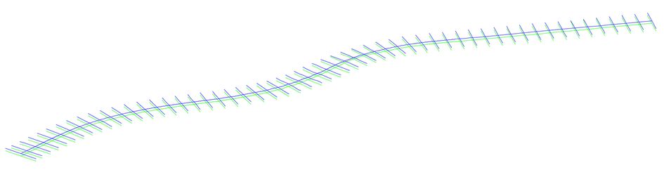
In our case Terrain _02 is coloured blue, so you can more easily imagine the result of the projection.
 1.2 Drape alignment and sample lines onto the third terrain
Then you do the same with the third terrain. And, if you have even more terrains in the drawing, then you repeat this for those other terrains.
1. Click on the Drape command.
2. In a new dialogue box select a second surface, on which you want the axis to be projected.
The data source can be different digital terrain models (CGS Surface, Civil 3D Surface, BricsCAD surfaces or basic 3D faces) or points from the file.
3. Confirm by pressing the OK button.
2. Draw a profile view
Insert the main terrain (Terrain_01) with the Draw Profile View command.
1. Click on the Draw Profile View command.
2. Select Plateia table type, for input data use *Current drawing* or select another drawing to which your alignment design was saved if you started to draw the profile in a new drawing.
3. Select a surface named 0. This is the main terrain you defined for this axis in the Parameters (Alignment manager) dialogue box.
4. Press OK and define the location of the profile view in the drawing.
3. Insert second and third terrain in the profile view
3.1 Insert the second terrain in the profile view
Insert second and third terrain in the existing profile view with the Draw Profile View command.
1. Click on the Draw Profile View command
2. Now select the second terrain from the drop-down menu.
3. Confirm by clicking OK.
3.2 Insert the third terrain in the profile view
1. Click on the Draw Profile View again.
2. Select the third terrain.
3. Confirm by pressing the OK button.
4. Draw a profile
Design a profile with the Draw Profile command.
1. Run the Draw Profile command.
2. Tangent can be drawn by selecting vertex points in the drawing.
3. Press Enter to finish
A warning message about the minimum allowed vertical-curve radius can appear.
4.1 Edit profile
You can then edit the geometry of the drawn tangent with the Editing tools.
5. Calculate Superelevation
1. Run the Calculate Superelevations command.
2. Calculate Superelevation dialogue box opens.
3. First define the area, where you want to calculate superelevation. Usually, you select the whole area.
4. In the next step define superelevation type.
5. Select pivot method: it defines the point on the lane about which the roadway is superelevated.
6. The next two settings (Attainment method in tangent-curve and Correction of attainment in spirals) are advanced, so leave them as they are.
7. At the bottom of the dialogue box specify limits.
8. On the right side, you can specify which superelevation line should be labelled.
9. Confirm by clicking OK.
6. Draw Cross-section Views
Insert the main terrain (Terrain_01) with the Draw CS View command.
1. Click on the Draw CS View icon.
2. Choose Plateia table type from the drop-down menu. Select *Current drawing* for input files or select another drawing if you started to draw a cross-section view in a new drawing.
3. Select the main surface from the drop-down menu. It is named 0.
4. Confirm by clicking the OK button.
7. Insert second and third terrain in cross-sections
Insert second and third terrain in the existing cross-sections in the same way as in the longitudinal profile.
7.1 Insert the second terrain in cross-sections
1. Click on the Draw CS View icon.
2. Select the second terrain from the drop-down menu.
3. Confirm by pressing the OK button.
7.2 Insert the third terrain in cross-sections
1. Click on the Draw CS View icon.
2. Select the third terrain from the drop-down menu.
3. Confirm by pressing the OK button
8. Edit cross-section tables
1. Run the Edit Tables command.
2. Click the plus and define a new rubric name (TERRAIN3) and column height (10).
3. Then click Save button.
4. After that define a table name and confirm by pressing the OK button.
5. Click OK.
6. Run the Draw CS View command.
7. Select TERRAIN3 from the drop-down menu.
8. Then click on the Setting button.
9. Check the box at the Elevation [m] and select TERRAIN3 from the drop-down menu.
10. Then click OK on this dialog and then on the Read terrain dialogue box.
9. Draw TCS Elements
Construct roadway section geometry with Draw TCS Elements tools. Plateia provides capabilities for designing and editing roadway cross-sections in a detailed way with almost no geometry limitations to the final project design.
The typical cross-section elements (TCS) group of commands contains commands for inserting individual TCS elements such as shoulders, embankments, substructures, ditches, pavements, etc. It is possible to insert TCS elements such as blocks, lines, points, etc.
10. Planimetry
Define a material area with the Planimetry command.
1. Click on the Planimetry icon.
2. Select the method Between CS, and define the first and last cross-section, between which you want to define quantities.
3. Specify the type of planimetry quantity. Automatic planimetry is divided into two types: surface and length planimetry.
4. Specify material.
5. In Settings, specify Planimetry-polygon definition:
- inner point: planimetry polygon is defined by selecting a point inside an area, surrounded by the planimetry polygon.
- between two polylines: planimetry polygon is defined by two polygon lines, bordering a surface. First defined so-called reference polygon line and then a second polygon line.
6. Confirm by clicking the OK button to draw completed polygons with hatches in their inner part.
11. Draw a 3D geological model
11.1 Draw missing TCS elements.
1. Click on the Line command in the Cross Sections ribbon.
2. Select the first and the last cross-section.
3. Select Between two elements option.
4. Define the element label.
5. Confirm by pressing OK.
6. Select a first and second element in the drawing.
7. Then repeat the same process on the other side of the cross-section.
11.2 Planimetry
When you have closed polygons in the cross-sections, you can start with planimetry.
1. Click on the Planimetry icon again.
2. Select the method Between CS, and define the first and the last cross-section, between which you want to define quantities.
3. Specify the type of planimetry quantity. Automatic planimetry is divided into two types: surface and length planimetry.
4. Specify material.
5. In Settings, specify Planimetry-polygon definition.
- inner point: planimetry polygon is defined by selecting a point inside an area, surrounded by the planimetry polygon.
- between two polylines: planimetry polygon is defined by two polygon lines, bordering a surface. First defined so-called reference polygon line and then a second polygon line.
6. Confirm by pressing the OK button to draw completed polygons with hatches in their inner part.
12. Create a 3D model
1. Run the Draw 3D Model command.
2. In Layout/alignment enter the alignment drawing, in Profile enter the drawing of the profile and in Cross sections enter the drawing of the cross-sections of the roadway. Data sources can be either in one group or in separate DWG drawings.
3. Select the alignment from the drop-down menu and define the starting and ending cross-section.
4. Check the boxes at the planimetry quantities you want to create a 3D solid model from.
5. Check the box at the Align option to connect the consecutive planimetry polygons along the alignment. Otherwise, it connects the adjacent planimetry polygons with sectional straight lines.
6. Confirm by clicking OK.